This is the first try of using the latest Bluetooth SoC from Nordic Semiconductor to drive a NeoPixel LED strip composed of 12 WS2812b LEDs.
WS2812b LEDs are full color LEDs that can be controlled individually via one single wire, also known as NeoPixel LEDs. I am not going to cover a lot of details about this LED but only the essentials.
The nRF52832 is the latest Bluetooth SoC from Nordic Semiconductor. It featured on chip Balun and a power processor packed with lots of NAND and RAM space, and come with support on Bluetooth 4.2. We are going to use this chip to drive a NeoPixel strip consists of 12 individually addressable full color LEDs, and later in another blog, we will connect it using Bluetooth LE.
Overview
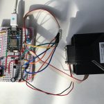
The photo above shows all the components needed to build the thing, including the nRF52-DK development kit from Nordic Semiconductor, a voltage level shifter, a short strip of WS2812b NeoPixel, and a USB power bank capable of providing at least 2A of current, plus a few jumper wires.
WS2812b
WS2812b LED is a LED integrated with a controller chip. The controller chip drives the three color LEDs as well as propagate the control signal to other LEDs.
The format of the signal is very simple: 3 colors for each LED, ordered as Green-Red-Blue with MSB sent first.
The timing of the signal is as follows:
A ‘0’ is denoted by a 0.4µs high followed by a 0.85µs low voltage.
A ‘1’ is the reverse of a zero, i.e. a 0.85µs high followed by a 0.4µs low voltage.
A low of 50µs or longer denotes a Reset.
The circuit
Voltage Shifter
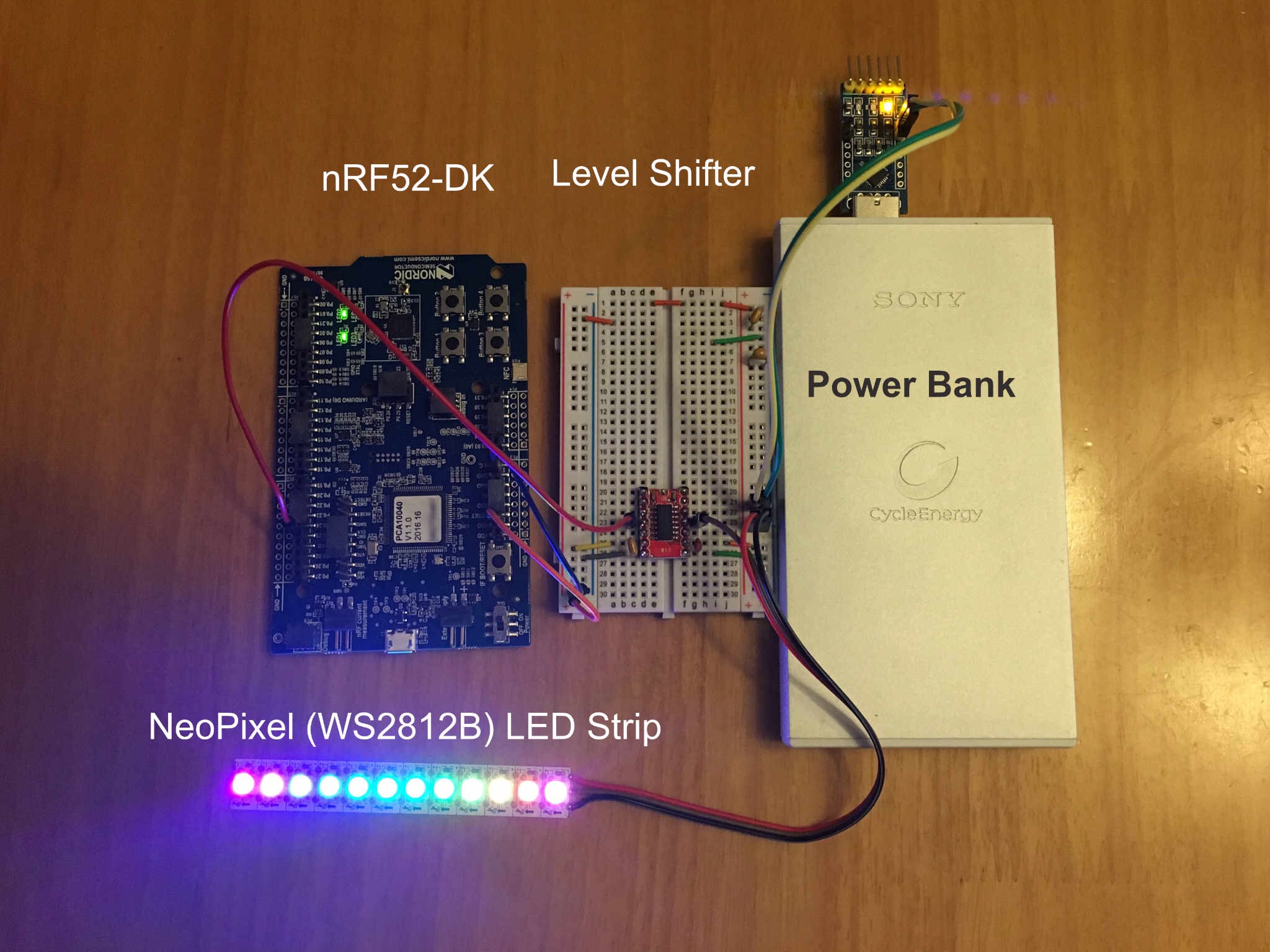
I was hoping there was no need for any more components required other than the nRF52832 and the LEDs, believing the output of the SoC is enough to drive the LEDs like the Particle Photon. I was wrong. The output of the nRF52832 cannot drive the DI of the LED strip, I have ended up to use a logic level shifter to raise the signal to 5V from 3.3V. (To be fair, according to the datasheet, it says 0.7VDD and that is 4.5V under a 5V supply). I chose the (Takafumi Naka recommended) TXB0104 module for this work. It’s 4-channels are a bit overkilled but I couldn’t find any TXB0101 (single channel) module out there and the chip is only available in SMT package.
Schematic Diagram
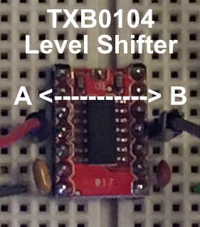
The circuit is very simple, most of the things are already taken cared by the Bluetooth SoC and the LED strip, leaving only one external component – the voltage shifter:
On the left hand side, one connects 3 wires to the nRF52832 – VDD, GND and SDOUT (defaulted to 11 in my source code but you can change it to any GPIO you can use on the nRF52832 by changing the config.h).
On the right hand side, one connects also 3 wires to the WS2812b LED strip – +5V, GND and DI.
You will also need a 5V external power supply that can deliver enough current to your worse case scenario.
Power Supply
Power supply to the nRF52832 is very simple, it can take anything from 1.8V to 4V and it consumes only very little current (in the range of uA). The same goes for the Voltage Level Shifter.
The LED strip, however, is very different. Each LED color consumes around 20mA in it’s maximum brightness (255) and linearly fall with the brightness value to 0mA (0) with a static current of ~1mA. That is, 10 LEDs on strip with full brightness will consume (60+1)x10 = 610mA; and 310mA in half-brightness.
You must therefore power the LED strip using a separate power supply that can deliver enough current for your LEDs.
Software
The software is adapted from the one written by Takafumi Naka in his blog here. The version Takafumi Naka was using is only for nRF5 SDK 11 and does not work out of box on the latest SDK 12.1.0. However the changes are mostly superficial and can be quickly ported to SDK 12.
The timing logic is defined in the file i2s_ws2812b_drive.c , and the supporting functions are defined in the file ws2812b_drive.c
The file rainbow.c provides the rainbow pattern to the LEDs.
Firmware
You can just download the .hex file from my repository on Github and burn this to your nRF52832.
If you want to customize it or modify it for your own use, you will need to get the source code, also from my repository on Github. I will also assume you are familiar with the nRF5 SDK 12.1.0 and is comfortable working with the gcc compiler or able to move a gcc-based project to your environment, whatever it is.
Create a directory inside your nRF52 examples/ directory, e.g. works/, then place the directory containing the sources inside it. You should ended up with something like nRF52/examples/works/nRF52_WS2812B/
Compile
You will need to have at least the nRF5 SDK 12.1.0 installed on your computer and a compatible compiler in order to compile from the source.
Assuming your nRF5 SDK is installed in ~/nRF52/, simply change directory to pca10040/armgcc and type make. E.g.:
h:~ u$ pwd

/h/u/nRF52/examples/works/nRF52_WS2812B/

h:~ u$ cd pca10040/armgcc

h:~ u$ make
Flash
A make flash will burn the firmware to the nRF52832. This version has not used any BLE functionality so there is no need to perform a make flash_softdevice
Away from the Development Board
The development board allows you to flash an external nRF52832 easily with only 3 wires (SWDIO, SWDCLK, GND). Get a nRF52832 module and flash it with the firmware, connect it to a battery and the voltage level shifter and off you go, a compact light show.
Todos
Next I will add the BLE functionality to it so that we can control the pattern shown on the LED strip using a smartphone, or from NodeRed using noble.