This is the part one attempt to make a €2.5 kitchen scale connect to the cloud.
Part 1 is aimed to hack a cheapo kitchen scale so that we can get the weight readings from a Spark Core.
Part 2 will be to connect it to the Internet so that the readings can be push to a smart device, or recorded for read back later.
Part 1 – Hacking the kitchen scale
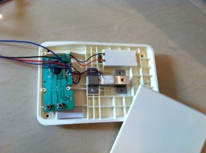
Opening up the kitchen scale, there is the load cell and the 4 wires that lead to the circuit board. These 4 wires needed to be connected to the HX711 module board so that the measured weight will be able to read digitally by the Spark Core. These wires are usually colored as Red, Black, Green and White and they need to be connected to E+, E-, S+ and S- respectively on the HX711 module board.
This is a close up of the HX711 module board. The right hand 4 wires are the ones lead out from the kitchen scale’s load cell.
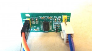
The 4 wires on the left hand side of the module are connected to the Spark Core for signaling and reading the values returned by the ADC. The clock is supplied to the PD_SCK and data is read out form the DOUT pin on the module. Any two digital I/O pins on the Spark Core could use for such purpose. The other two pins on this side of the module are the power supply. The recommended operating voltage is 2.6~5.5V. I used the 3V3* output from the Spark Core. The 3V3* is a filtered 3.3V power supply give a good and smooth 3.3V DC suitable for use with this sensitive equipment.
OLED Display
Next to connect the OLED display for local display of the weight as well as for calibration and debugging use.
The OLED used here is a 128×64 1.3″ OLED with built-in character ROM. The OLED is addressed using I2C and the character ROM via SPI. Both I2C and SPI have their specific pins on the Spark Core so they must be followed.
Writing to the OLED is as straight forward as writing to any I2C devices. Reading the bitmaps from the character ROM is a little bit tricky as I have found that reading it too fast will have bits dropped here and there. So a slight delay is inserted to prevent this. Other than this, it is just a matter of looking up the address in ROM for a particular character, send the READ command to the ROM with the address, and read out the bitmap returned then send them to the OLED for display.
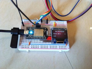
The current time as well as the version number are also set to displayed on the OLED just for convenience.
TARE
The tare is implemented as a simple falling edge interrupt to set the offset of the reader.
Calibration
Calibration is done using some known weight. As I do not have those standard weights, I can only use another kitchen scale to help to do the calibration.
A function is written so that it takes a value sent through the Cloud API and start the calibration process to calibrate to the weight specified by that value.
A simple Apple Script was created to send this value to the Cloud API. You can find it here.
Putting it altogether
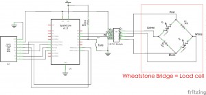
The following is the schematic for connecting all the component. In the schematic, the Wheatstone Bridge is the load cell itself.
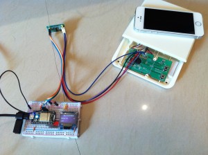
Altogether it looks like:
You can find the source code here. They are all under the MIT license.