A Certain Cheerlights Clock
Once upon a time, people tell the time by looking at the sun dial, today, we can tell the time by sending a simple query to a RESTful interface …
Ok, it was a nightmare, alright. However, having a spare meter of Neopixel LED strip of 60 LEDs/meter, I was thinking what to do with it. It sounds such as waste to use it just for illumination only (though I might do it in the near future with another spare meter or two of this thing, stay tuned). So I tried to make a clock out of it. A clock that connect to the Internet, not for telling time, but to become yet another Cheerlights.

The making
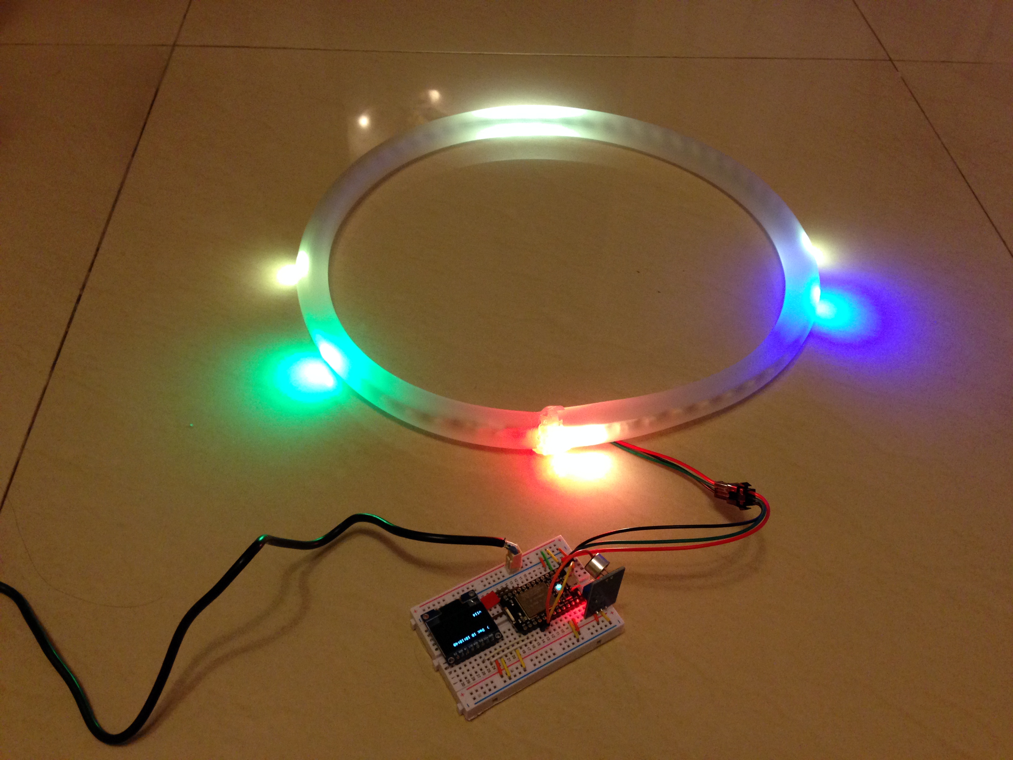
Using the same kind of LED strip as in the other Cheerlights project, a simple program was written on the Spark Core to show the current time on the strip. Since the strip has exactly 60 LEDs controllable individually, it can then be used to show the hours, minutes and seconds. I use Red to indicate the hours, Blue for the minutes and Green for seconds.
I also drew the 15 minutes marks using Yellow color.
The LED strip was instituted into a 1m long semi transparent PVC hose. The hose was then stitched together (since I have found no glue that can glue together the ends).
The PVC hose was bought form some aquarium shop.

The hardware
A Spark Core is used to drive the signal of the LEDs. An 0.9″ OLED is used to display some status such as the current time (yet another clock) and also the current Cheerlights color.
I have also connected a sound sensor to the clock so that when there is a loud clap, the clock will display a rainbow light show for a few seconds. However, this proved to be problematic, see below for more.
Unlike my other Cheerlights project which uses a 12V power supply (since it was what I had back then), this time I used a 5V 4A power supply bought from a second hand shop.

Below is the schematic diagram for the hardware setup

The software
The source code for the wall clock is available here on Github.
Credits go to Technobly for porting the Adafruit source to drive the Neopixel LED strips to the Spark Core.
The problem
It was fun to add the sound sensor since it gives some life to the dumb wall clock. However, the introduction of the sound sensor has caused the whole setup to become very unstable. The Core will just stopped working for no apparent reason after some time. I still am not sure about the cause but suspect it was due to the interferences between the Timer interrupts used to drive the LED strip and the interrupts from the sound sensor. Therefore, I finally decided to disable the sound sensing to get a stable, 24×7 running Cheerlights clock.